
NES board controller connectors. Solder points.


Connectors desoldered. A nice 15 pin connector from an old VCR.


Two 7 pin NES connectors connected to one 15 pin.


Routing of cable. Pins soldered to back of parallel port.


HD power/ground for controllers. Routing of cables.


More routing and hot glue.


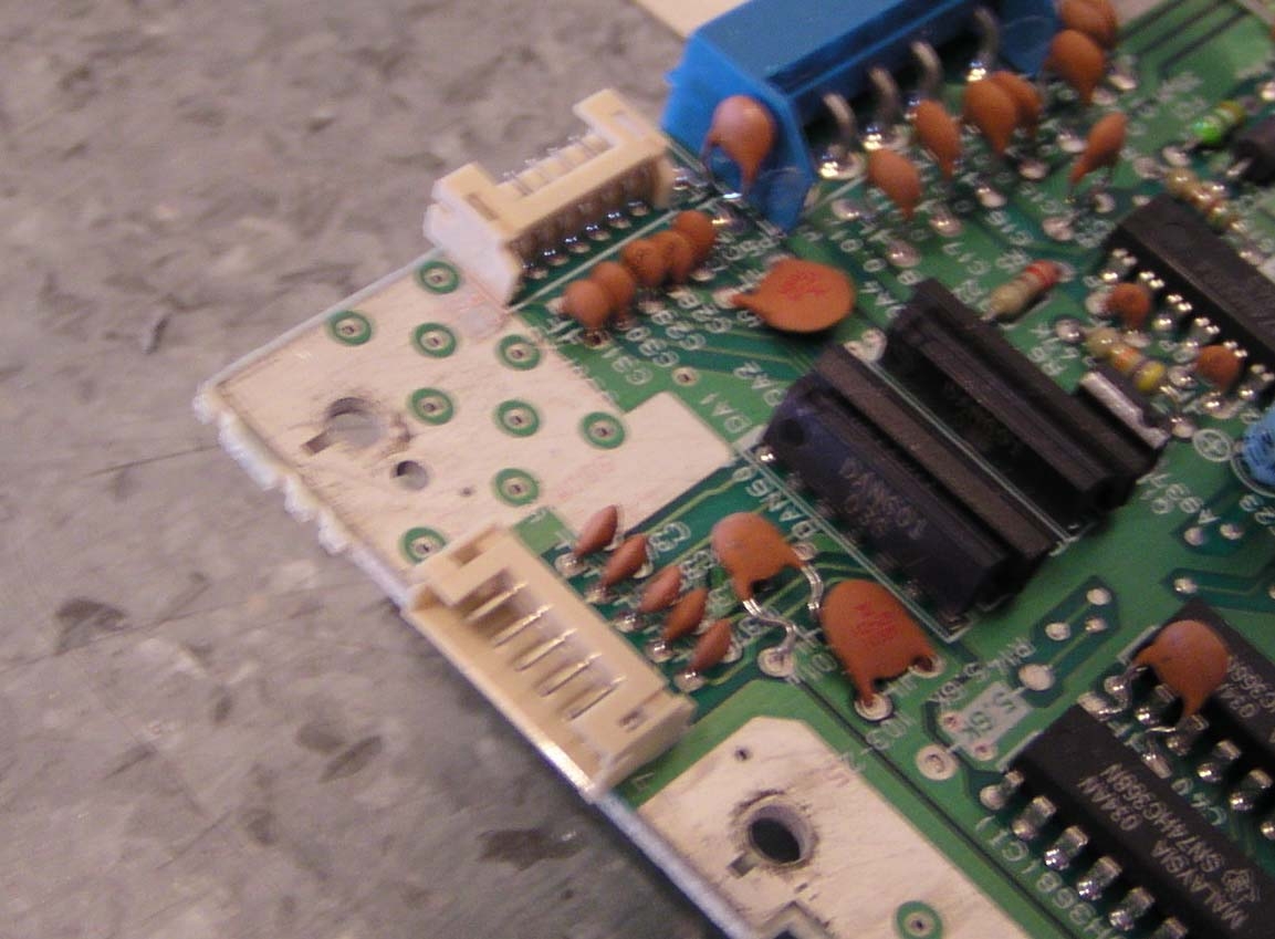
Added leads for more controllers. Connections on pins 2,3,10,11,12,13.


Cable routing. The Four Score.


Four Score open. Connector open.


Old controller. Old controller end.


Original connection. New connector, DIP switches.


Rear hole larger. First wire connection attempt.


Hot glue. Pre fit and test.


Solder on pins I cut, oops. Final connector.


Rewire and cuts on circuit board. Plug cover hole enlarged.

Final. Test of controllers good.
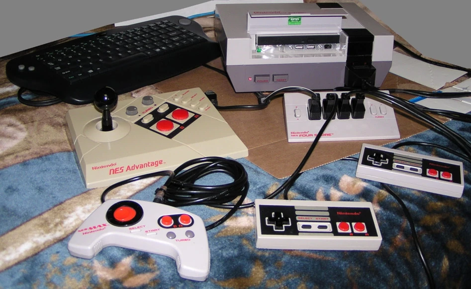
Four Score
To hook up 4 controllers you need 8 wires.
The 4S only has 7 wires, so I took apart another controller,
and used its wires to hook up controllers 3 and 4.
After the first test when I press the A button all buttons
would come on (yea that problem). So I started cutting into
the circuit board to isolate each controller plug. I had
wanted to just flip some switches inside and connect the
original plug and have it work with a unmodded NES. That
didn't happen. So I isolated the circuit board and got
controllers 1 and 2 working, but no response from 3 or 4.
So I ohmed the wires and found that the wires from the
controller I took apart had half the resistance of the other
4S wires. So I rewired and used the low ohm wires for the
power and ground. Now it worked.


These are the areas I cut. And these are some common connections, except yellow.
Blue is ground. Purple is power. Orange is DB25-2. Brown is DB25-3.
Yellow is DB25-10,11,12,13.

This is the way I wired it up.
I used DB25-11 instead of DB25-15 because I soldered to the inside of
the parallel port. If you do yours externally you should use 15.
Now you install the DirectPadPro software, and choose "5" Nintendo
controllers( "4" if you used DB25-15) and continue.
Once all 5 are installed, go to the device manager and under
"human interface" disable the 4th controller, there is two
places you need to do this in the device manager(ignore if you used DB25-15).
Now in the control panel you will have 4 controllers.
Go to each ones properties and disable force feedback.
Now test and cal each to make sure they work.